


The right screwdriver for all screws in this camera is clearly JCIS #0.
Originally I had to use my own "screwdriver" grinded down from an old saw blade 0.4mm thick, because Phillips screwdriver is inappropriate for these screws.
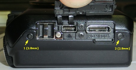
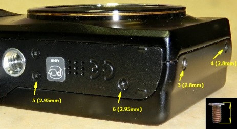
Six screws and three locks hold the rear cover. Because the length of all screws is not equal, it is noted in parentheses.
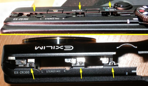
To say the truth, I do not know how to release those locks easily. I just tried to apply more and more force hoping that the glass of the rear cover will survive it :‑( .
The images shows positions of locks.
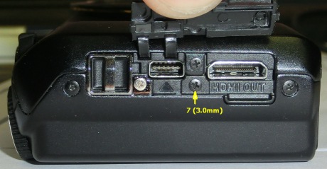
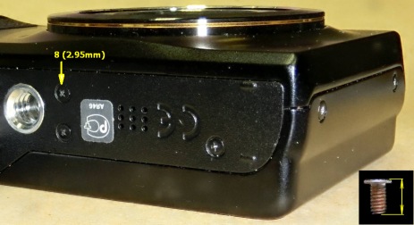
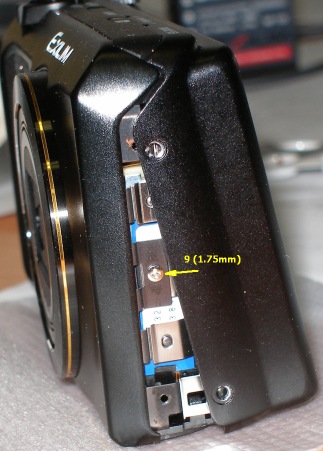
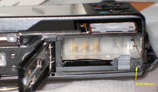
Another 5 screws hold front cover (and some locks, which are easy to release, but it can be difficult to get them all to the right places during reassembling).
 |
 |
 |
 |
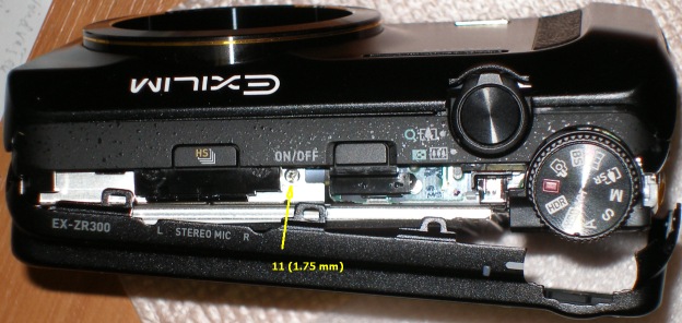
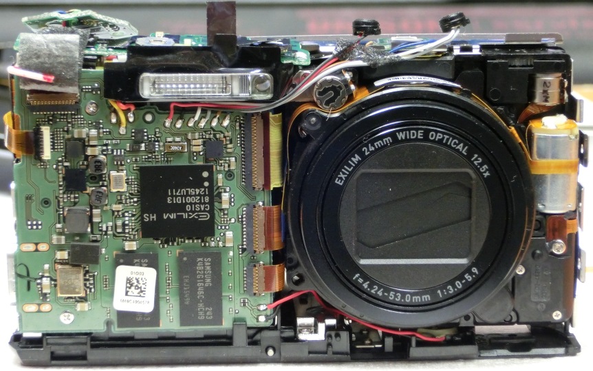
Front cover removed:
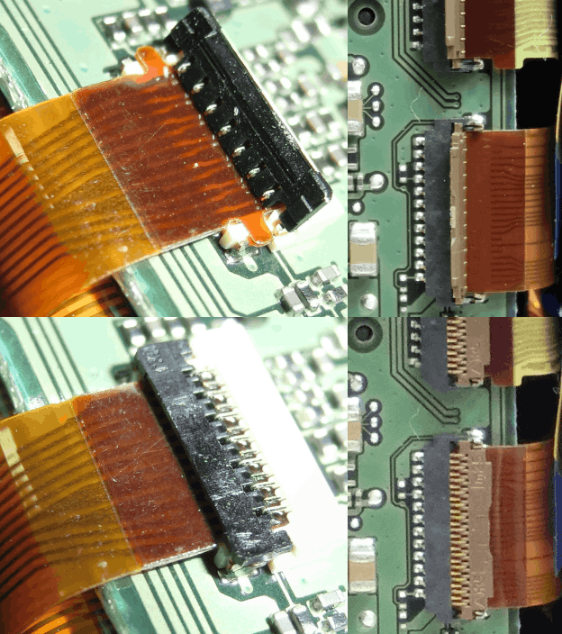
To say the truth, I have no idea how to unlock the display connector and release the display FPC.
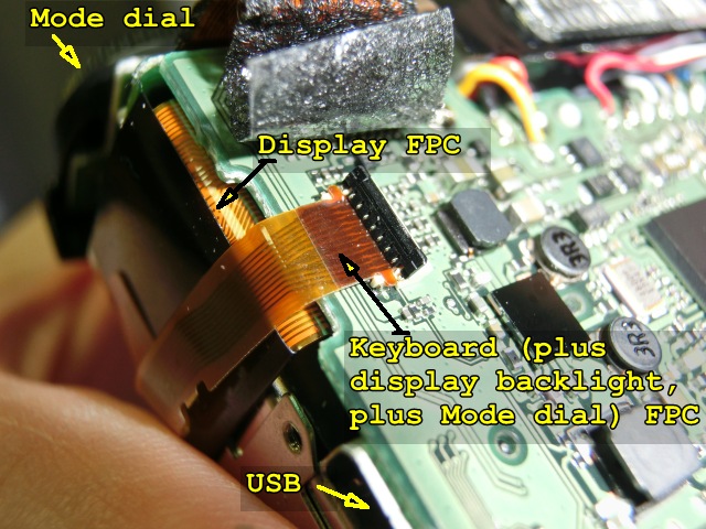
Because I needed to remove the mainboard, I tried to do it with the display cable connected. Removing the mainboard involves unscrewing it (2 screws 3.0mm), disconnecting flat cables, desoldering battery and speaker wires, releasing microphones and undoing the "HS" switch (which is held in its place by double-sided adhesive tape). But still connected display cable, together with the plastic entry to memory card slot makes almost impossible to get the mainboard out. But eventually, I managed it somehow.
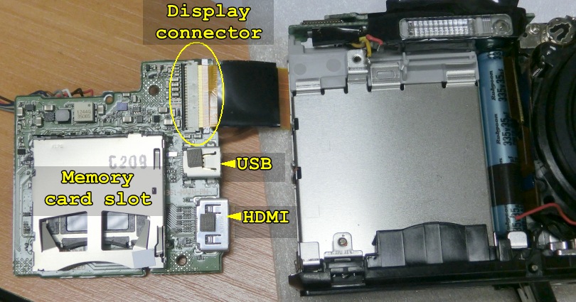
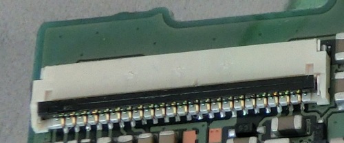
Than it is easy to release the lock of the connector and remove the display FPC. Note that unlike the other connectors on the mainboard, this one has its actuator on the opposite side than the FPC is inserted.
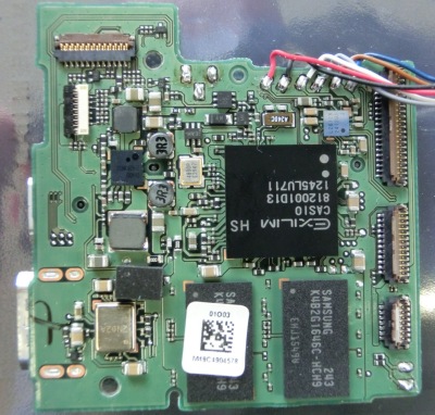
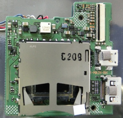
The top and bottom of the EX-ZR300 mainboard:
 |
 |
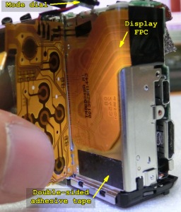
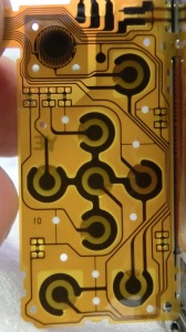
Keyboard details:
 |
 |
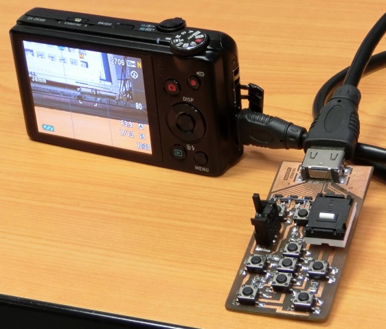
The reason why I disassembled the camera was the intention to change its functionality. Especially for stacked macro photography, I need complete remote control, because even mounted on tripod, camera slightly moves when shutter and other buttons are pressed. So I decided to sacrifice the HDMI output and use its connector for external keyboard.
All comments are welcome at mweb09 cesnet
 cz .
Including language corrections :-) .